The purpose of the test is to determine the performance and leak tightness of two pipes connected by an elastic sealing ring. The pipe section (two pipes jointed together by the ring) is submitted to pressure and vacuum during angular deflection in four directions while detecting if any leakage occur. The test procedure is mainly performed on plastic pipes such as polyvinyl chloride, polyethylene, polypropylene.
During the last 50 years our focus has been developing best in class test equipment for the pipe industry. SCITEQ equipment and software for pipe testing is designed in Denmark and manufactured in our production facilities and with our European sub-contractors. The leak tightness tester is designed to perform tests according to international standards similar to the SCITEQ SIGMA test system for hydrostatic pressure.
Watch this short video for an introduction to SCITEQ leak tightness test for joint pipes.
The fully customizable test sequence of the LTT can be configured for other test standard requirements additional to ISO 13259 (superseeding ISO 1277). The SCITEQ LTT also complies with the following standards:
The testing principle of ISO 13259 (superseeding ISO 1277) applies for thermoplastics piping systems for underground non-pressure applications. The test method is for leak tightness of elastomeric sealing ring type joints and comprises exposing the test pipe to a vacuum (internal negative air pressure) for a specific period, filling the test pipe with water and subsequently exposing the pipe to an internal hydrostatic pressure for a specific period. During testing, the joint will be subjected to deflection.
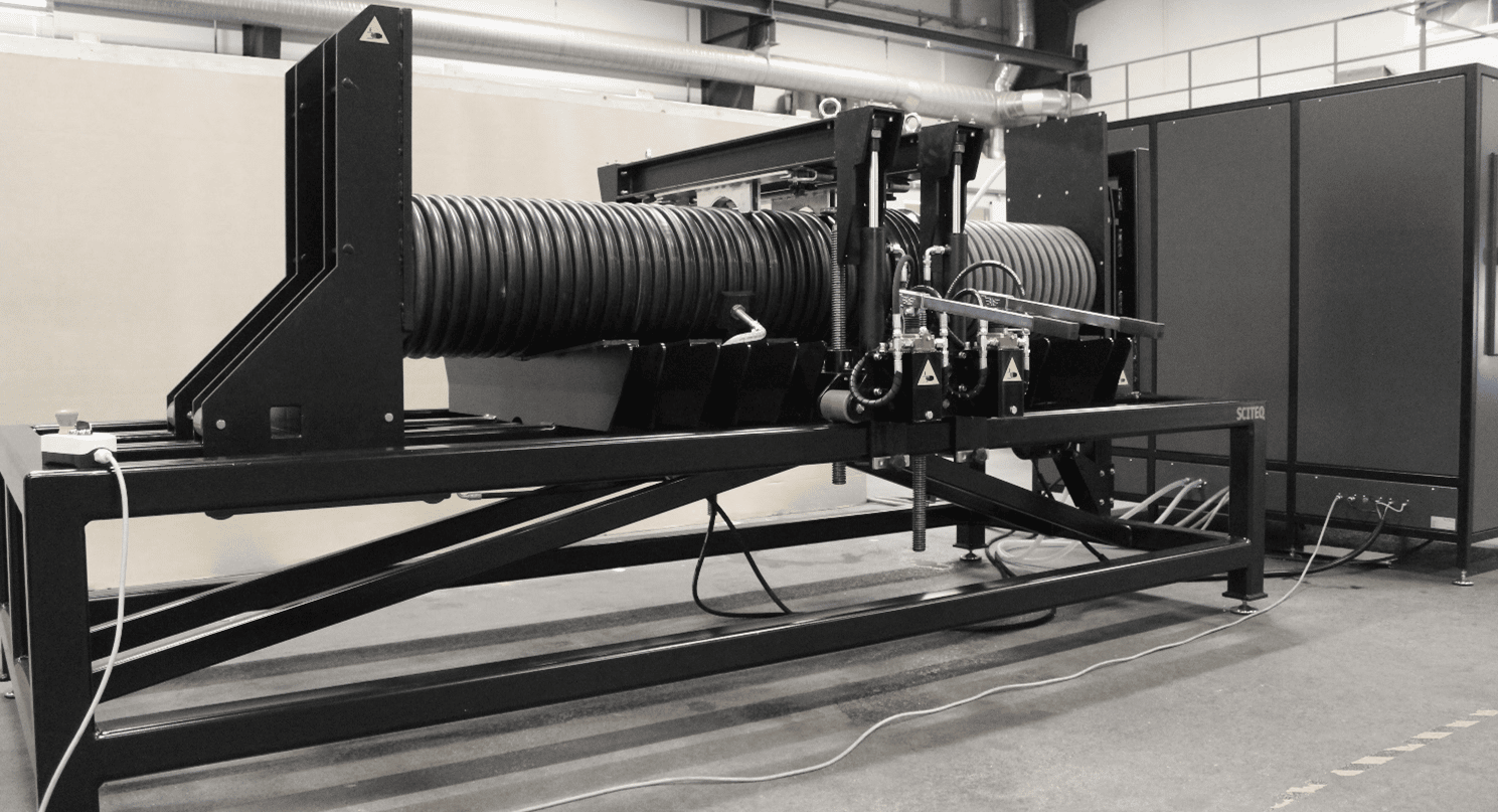
The SCITEQ Leak Tightness Tester (LTT) is one of the markets most durable, flexible and robust solution for testing joints of buried plastic pipe systems. The smart design of the LTT allows for fast adjustment and preparation of both corrugated and smooth wall pipes of up to diameter of 1200 mm. The technical cabinet features high quality components, that provides both vacuum and water pressure. The automatic deflection system and floating beams ensure a 100% correct diametric and angular deflection of the pipe of up to the 5° prescribed by standard ISO 13259.
The automatic water supply system also includes a bleed function that maintains pressure below maximum test pressure while the sample is filled. Furthermore, the built-in drainage system allow for easy and quick repeat of the test.
A test sample assembled from pipes and/or fittings is subjected to a specific initial internal negative air pressure followed by a low specific initial internal hydrostatic pressure and a higher internal hydrostatic pressure. During testing the joint may be subjected to diametric and/or angular deflection(s). The referring product standard specifies which of the test pressures and deflection conditions have to be carried out. Each pressure is maintained for a specific period during which the joint is monitored for leakage.
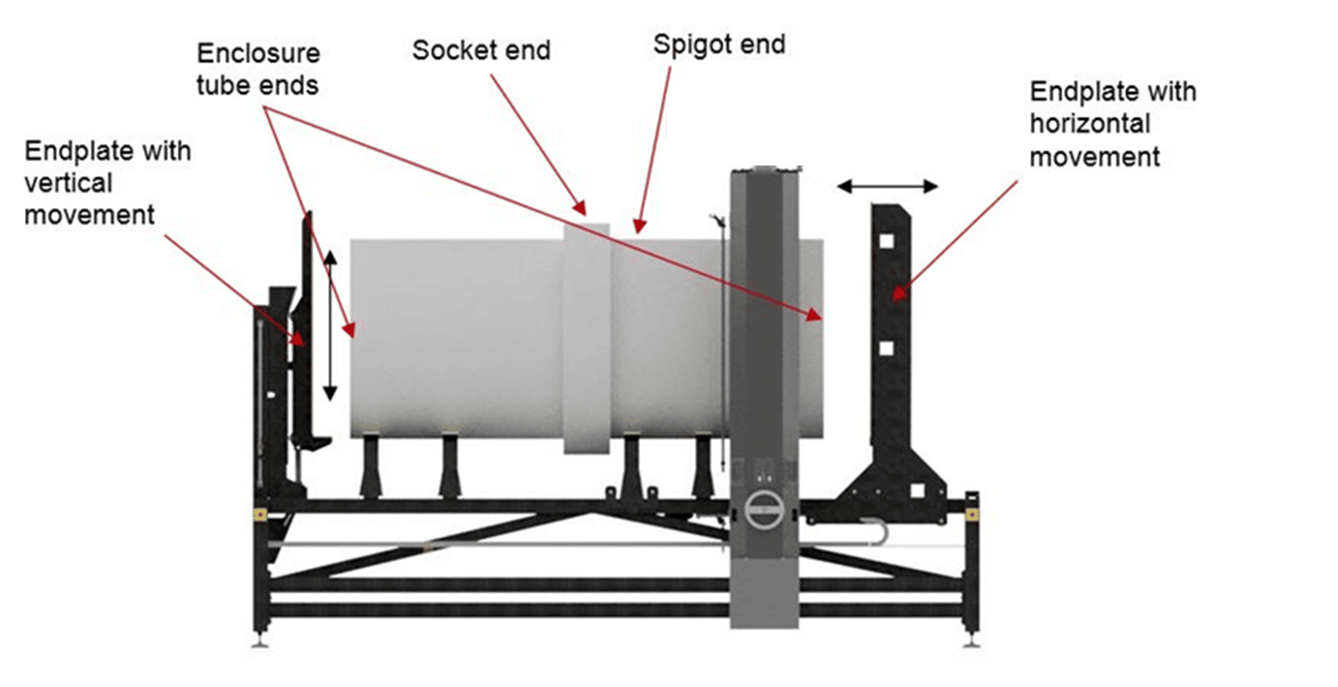
Two pipe sections are cut according to the standard for the test procedure. The two sections of pipe are then placed on the main frame of the machine, with the spigot and socket end facing each other in the middle (ready for joining).
End closures are mounted at the two pipe ends facing away from the spigot joint. Using the endplate, which can move in the longitudinal direction of the main frame, to press the two sections of pipe together the pipe samples are sealed.
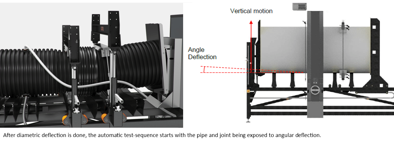
The SCITEQ Leak Tightness Tester seamlessly performs all steps of the test required by the ISO 13259 standard. After diametric deflection is done, the automatic test-sequence starts with the pipe and joint being exposed to angular deflection. Secondly, the pipe is exposed to a vacuum test, that tests the pipe and joint integrity.
Finally, the sample is filled with water and subsequently exposed to two steps of internal hydrostatic pressure
The system automatically monitors and logs the process in real-time, detecting any possible joint leakage. Once the test is completed, the automatic water drainage system drains the water, allowing quick repeat of the test. The system automatically monitors and logs the process in real-time, detecting any possible joint leakage.
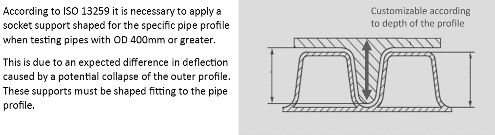
The compression clamps used for the test, are custom designed to fit the specific pipe structure. For pipes OD 400 mm or greater it is necessary to test with a clamp socket support, due to an expected difference in deflection caused by a potential collapse of the outer profile. These supports are customized according to pipe profile depth/design.
The main Frame
The machine consists of a frame with supports for placing of the pipe test sample. The towers can move back and forth on the frame enableing easy adjustment.
One of the end plates mounted at each end of the main frame can move in the longitudinal direction of the main frame. This movement of end plate enables that the two pipes of the test specimen are pushed together and joined. The opposite endplate is used to create the angular deflection of the joined test specimen. This endplate can move in the vertical direction and thereby forcing one end of the test specimen in an upward direction, while the rest of the pipe is held in a fixed position by the compression beams and towers.
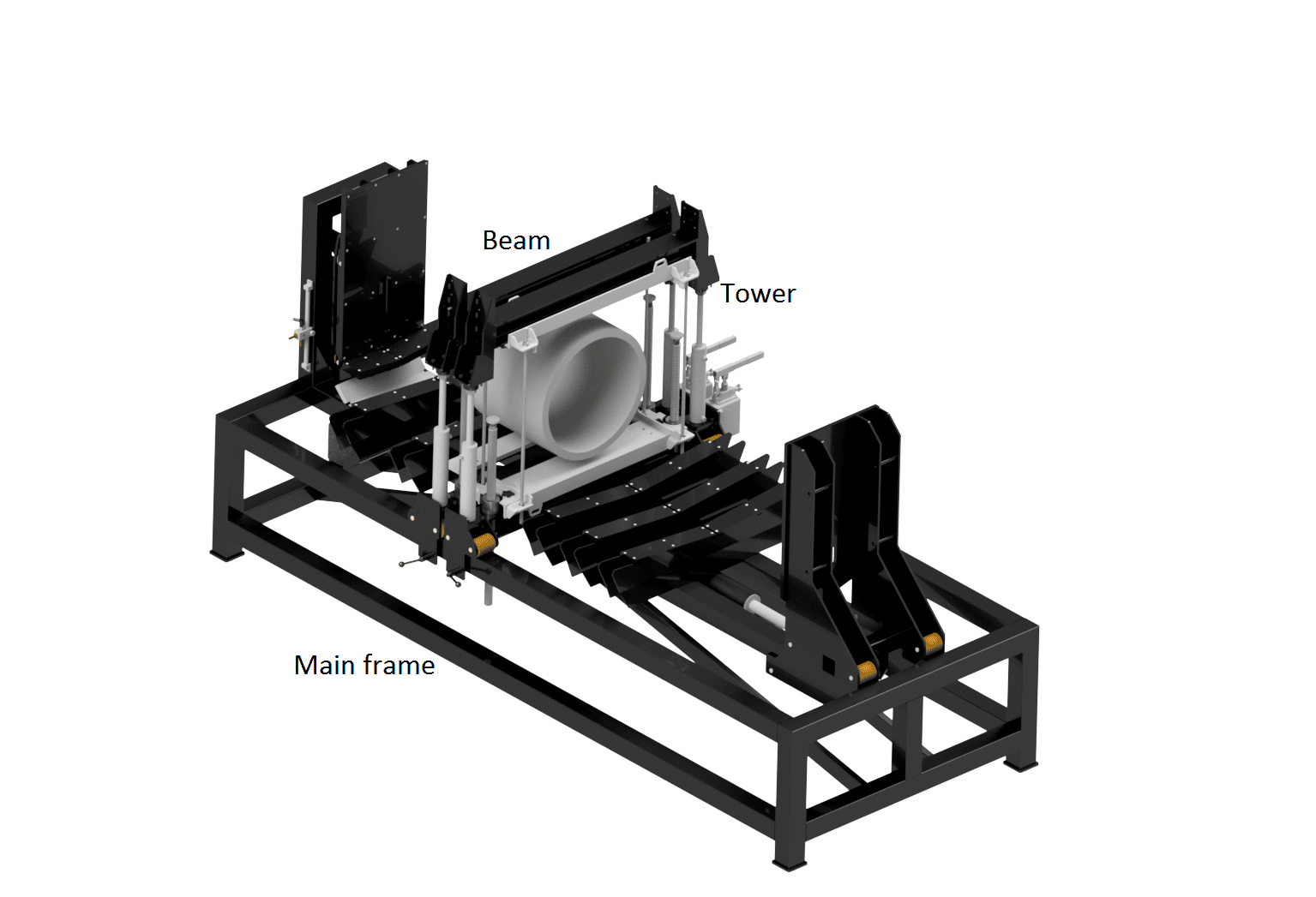
The towers
The mechanical components found of the tower are creating the structural deformation of the pipe test specimen. The deformation is created by electric motors and spindles forcing the beams to clamp onto the pipe structure. The tower is free to move in the longitudinal direction of the main frame, which allows applying structural deformation at any point along the test specimen.
The beams
The compression force generated in the tower is transferred onto the test specimen using a set of two beams. The two beams are placed on each side of the test specimen/spigot and as the tower beams are compressed, the pipe specimen is deformed.
In order to distribute the compression force from the beams correctly onto the surface of the pipe specimen custom designed clamps are mounted on the beams.
The deflection obtained by the tower can be maintained, without the tower, by mounting of threaded rods between the two beams in contact with the test specimen. Once the threated rods are mounted the beams can be disconnect from thevtower. A new set of beams can then be mounted in the tower and the machine is then ready to apply pressure at another point of the specimen.
The technical cabinet
Water pressure and vacuum is supplied by the technical cabinet built of high quality components. The hydraulic system installed inside the technical cabinet is connected directly to actuators on the main frame. The water-air-systems creates vacuum and pressure during the test sequence, exposing to two steps of internal hydrostatic pressure. Vacuum loss detection under 5% as well as pressure loss detection under 10%.
Our leak tightness test for joint pipes is installed and used for testing in differerent industries such as pipe manufacturing, private and governmenal test institutions for both product approvals and research and development projects.
Please reach out to us to learn more about how the LTT system is put to use in the different projects we have installed world wide. Five recent installations for your reference:
Learn more about SCITEQ Leak tightness test
For a closer look at the LTT machine visit SCITEQ YouTube. Here you will find videos of the solution.
Contact us for further information
We are at your disposal for any questions, comments and suggestions. We look forward to hearing from you.
Feel free to contact us using the contact form below.
We strive to answer all inquiries within 24 hours (on working days).
